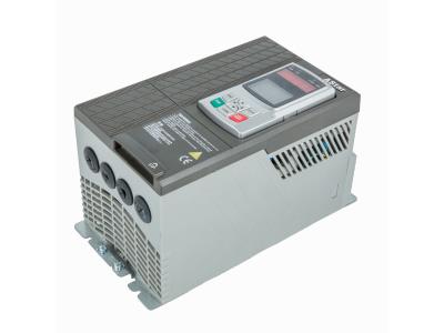
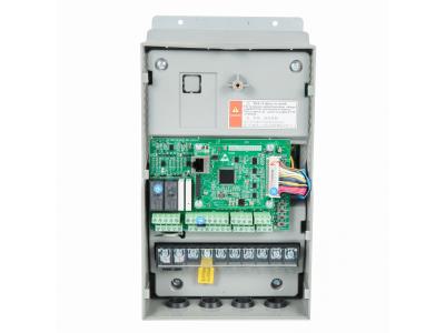
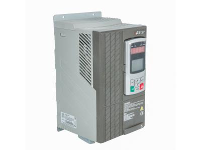
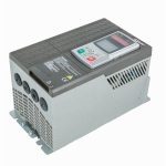
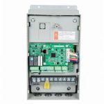
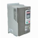
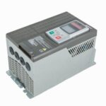
Variable Frequency Drive for CNC lathe

Inquire Now

AS180 Series VFD is an universal VFD desinged for the industry market. The product was adopted with the Germany technology, made in China, and combined with the characters of domestic applicationm, further strengthening the product reliablity and design for customer and the industry, with excellent performance of V/F control to perfectly satisfy a variety of light load driven application requirements.

Feature and Advantages


1.
High -efficient & energy saving operation.

2. Fast Dynamic Response
Advanced motor control can also quickly response to load change without PG Card.

3. Smooth tracking start
At any time, smooth start can be perfectly achieved without impacting the rotating motor.

4. Powerful grid adaptability
Automatic voltage adjustment function: when the grid voltage changes, the output voltage can be automatically kept constant. In the case of sudden loss of electricity, unique non-blackout function can keep VFD running.

5. Stable operation with low frequency and high torque.
Dynamic calcultion of IGBT internal temperature ensures that the IGBT module operates with the temperture limits, improving reliablity of the module.

6. Positive-reverse switch
When positive-reserve motor switch to the zero-speed, the phase of current has no change or oscillation, and speed has no ripple.

7. Papid acceleration
0.1s full load acclleration with fast torque response and low speed overshoot.

8. IGBT temperature protection curve
Dynamic calculation of IGBT internal temperature ensures that the IGBT module operates within the temperature limites, improving railiability of the module.


Intimate application function
* PID control dedicated menu to set PID parameters, calculate inside the VFD, without independent external regulator option.

* DC braking before operation: when the rotating direction of motor during free sliding is uncertain, DC braking automatically stop the motor before starting.

* For the square torque load of fan and water pump, high performance excitation control can make the motor run at the optimal efficiency point and achieve optimal energy saving effect.


Technical Paramters

Power input Input voltage 380-460V
Input frequency 45-65Hz
Accepting voltage change Voltage unbalance <3%
Voltage drop When the 3 phase AC380-460V, input voltage <AC300V, low voltage protection was implemented after 15ms.
Power output Voltage 0VAC ~ input voltage
Overload grade Stable running 40oC,heavy load 150%, 1min
Efficiency (full load) 0.94
Output frequency accuracy ±0.01% (digital command -10~+45oC); ±0.1% (analog command 25±10oC);
Digital input/output Optical coupling isolation input 7 channels, 24V high and low level can be set, input function can be defined
Open collector output 2 channels, output function can be defined
Relay output 2 channels, normally open contacts, contact capacity: inductive, 1.5A/250VAC, output function can be defined, 2 channels, dual normally open/closed contacts, contact capacity: resistive, 4.5A/250VAC or 4.5A/30VDC; inductive: 0.4A/250VAC or 0.4A/30VDC, output function can be defined
Analog input/output Analog voltage input 2 channels, accuracy 0.1%; voltage -10V ~ +10VDC or current 0~20mA optional signal
Analog voltage output 2 channels, accuracy 0.1%; voltage -10V ~ +10VDC or current 0~20mA optional signal
Control characteristics Carrier frequency 1.1-8KHz; carrier frequency can be adjusted automatically according to load characters
Frequency setting resolution 0.01Hz (digital command), ±0.06HZ/120Hz (analog command 11 bit + no signal)
Running command channel Given operation panel, given control terminal, given communication
Frequency given channel Give operation panel, given digital quantity/analog quantity, given communication, given performance function.
Torque improved Automatic torque improved, manual torque improved.
V/F curve User defined V/F curves, linear V/F curves, and three reduced torque characteristic curves
Automatic voltage adjustment (AVR) The duty ratio of output PWM signal is adjusted automatically based on the fluctuation of bus voltage, to reduce the influence of grid voltage fluctuation on output voltage fluctuation.
Electricity loss and keep running process In the case of instantaneous power off, achieve uninterrupted operation through bus voltage control
Direct current braking capability Brake current: 0.0~120.0% rated current
Characteristic function Parameters copy The standard operation panel can upload and download parameters and indicate copy process
Process PID Used for closed – loop control of process quantities
Common DC bus All series can achieve the power supply of common DC bus for multiple VFD.
Motor protection Rotor block, motor overload, speed limitation
VFD protection Output current limited, VFD overload, IGBT overload, under voltage / over voltage of input power, under voltage / over voltage of DC bus, IGBT over heating, power faulty, analog input signal loss (loss speed reference), communication abnormality, self-tuning faulty.
Environment condition Operation place Installed vertically in a well-ventilated electrical control cabinet. Horizontal or other installation is not allowed. Cooling medium is air. Installed in environment without direct sunlight, dust, corrosive gas, flammable gas, oil mist, steam, or water.
Environment temperature -10 ~ +40 oC
Used in diminished temperature >40 oC, a rise of 1 oC, rated output current is reduced by 2%, the highest temperature is 50oC
Altitude <1000m
Used in diminished height >1000m, a rise of 1000m, rated output current is reduced by 1% (up to 3000m)
Environment humidity 5 ~95%, without condensation
Vibration (transport) 2 f < 9Hz, 3.5 mm; 9 f < 200Hz, 10m/s2, 200 f < 500Hz, 15m/s2
Vibration (installation) 2 f < 9Hz, 0.3 mm; 9 f < 200Hz, 1m/s2
Storage temperature -40 ~ +70 oC
Protection grade IP20
Control panel Type Movable
Length 1m, 3m
Connector RJ45
LCD text display 4 row
LED display 5 bit
Visible LED indicator 4 pcs
key 9 pcs
Others Cooling way Force air cooling
Installation mode Installed in cabinet with wall-mounted
Certificate CE


Stable running 40 °C, heavy duty loading Dimension
VFD Model
AS180
Rated input current (A) Rated output current (A) Adaptive motor
(Kw)
Overload 120% (1min)
Output current (A)
4T07P5 16 15 7.5 18 A1
4T0011 21 20 11 24 A2
4T0115 30.5 29 15 34.8
4T18P5 38 36 18.5 43.2 A3
4T0122 46 44 22 52.8
4T0030 59 56 30 67.2
4T0037 75 72 37 86.4 A4
4T0045 94 90 45 108
4T0055 115 110 55 132 A5
4T0075 154 148 75 177.6
4T0090 183 176 90 211.2 A6
4T0110 216 208 110 249.6 A7
4T0132 261 252 132 302.4
4T0160 306 296 160 355.2 A8
4T0185 367 356 185 427.2
4T0200 402 390 200 468
4T0220 427 415 220 498
4T0250 481 468 250 561.6
4T0280 533 520 280 624 A9
4T0315 614 600 315 720
4T0355 664 650 355 780
4T0400 755 740 400 888

SMT15.jpg

Product Inquiry Form